
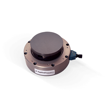
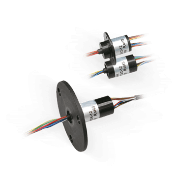
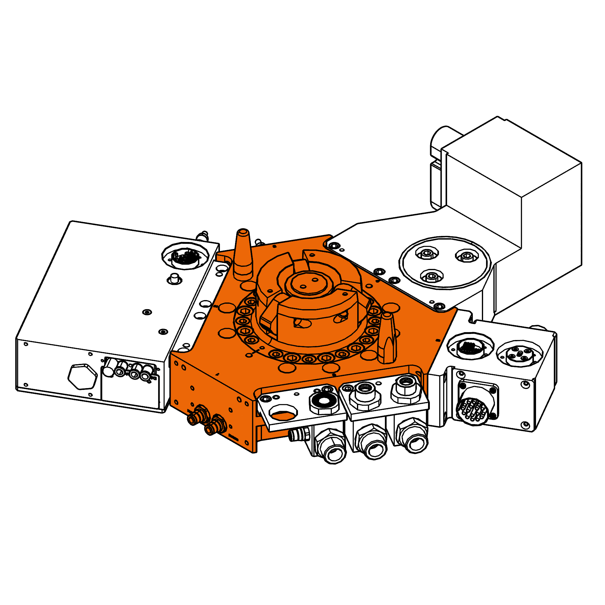
Slip Ring | 20 circuits | SVTS F 01-S-A-03/17

Flat design, 40mm through bore, 17 signals circuits and 3 power circuits

This Slip ring is designed for signal and power transmission where height is limited.

The SVTS F series is characterized by a through hole and uses a special technology. It allows to get multiple contact points between brushes and rings, low contact electrical resistance, reduced noise and low wear. Their special design comabines a maximum amount of circuits while keeping height size limited. THere are a lot of customization possibilities and these slips rings do not require any lubrication.

Advantages

  • Through hole 25-38-50 or 60 mm
  • Power circuits
  • Low friction torque
  • High lifetime and reliability
  • Compliant to CE and ROHS

Benefits

  • Flat design allowing to keep small machinery dimensions
  • Low maintenance
  • Good quality/price ratio

At your service

Need help in selecting the right product ?

Need more information ?
Contact us


SVTS F 01-S-A-03/17
Circuits 17 x 5A, 3 x 10A
Outside Diameter 180.0 mm
Inside Diameter 40.0 mm
Overall Length (L) 40.0 mm
Protection rating IP 51
Data Transfert <=100Mbit/s
Mounting Thru-bore 40mm

Mechanical features

Nominal speed 0-250 rpm
Temperature range -20°C to +80°C (-40°C as option)
Contact gold-gold (alloy)
Bearings Miniature high-precision stainless steel ball bearings
Connector -
Mounting Al

Electrical features

Voltage 400 VDC/VAC,240VDC/VAC
Cables Silver plated / PTFE insulated / colour coded
Cables length 250 mm standard (other length on request)
Dielectric voltage strength 500VAC @ 60Hz @ 60 sec
Insulation resistance >500MOhm/500VDC
Dynamic contact resistance <10mOhm @ 6VDC and 500mA (@ 5rpm)
Expected lifetime 107 revolutions (depending on speed, environmetal conditions and size)

Customisations

  • Cables
  • Materials
  • Mechanical design
  • Flange

Notice : The provided technical data are the higher limits recommended in static condition. To obtain the correct dimensioning of the product, it is necessary to hold account of all the applicable dynamic forces, including the inertia of the manipulator, the configuration of the tools and the external forces applied.

Drawings
Steps