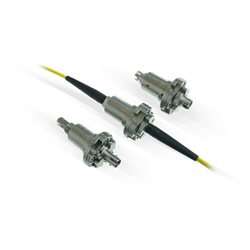
Rotary Union| 3 passages |GP(S) 131

Versatile, efficient and multichannel

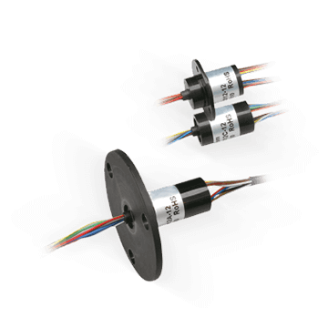
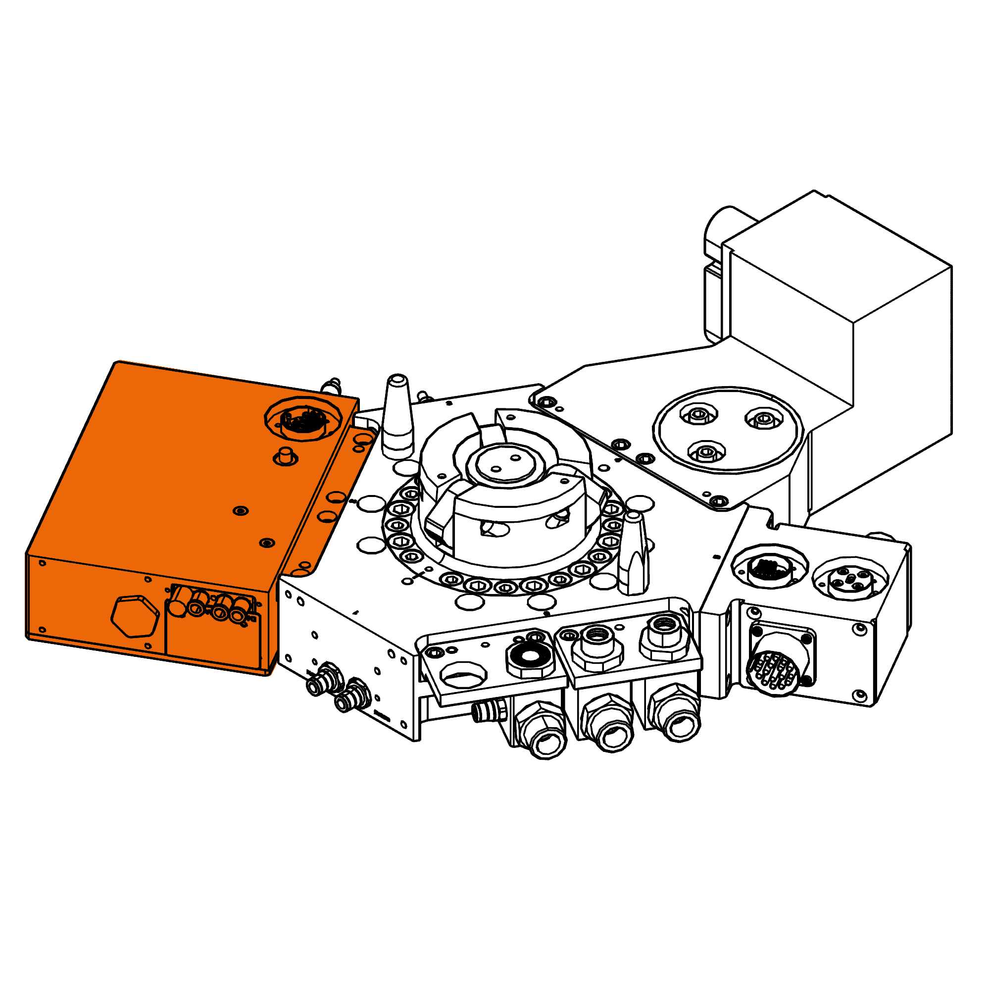
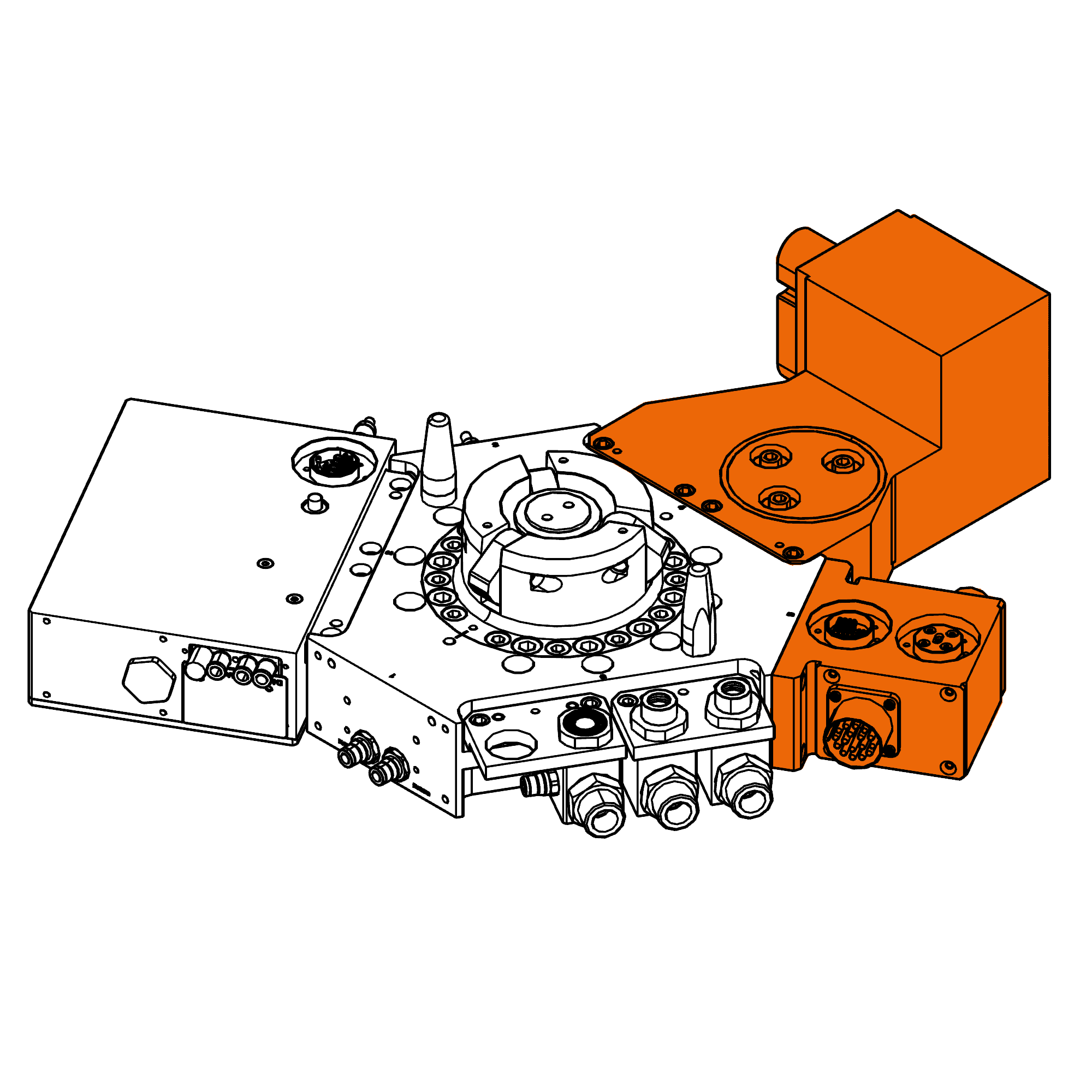
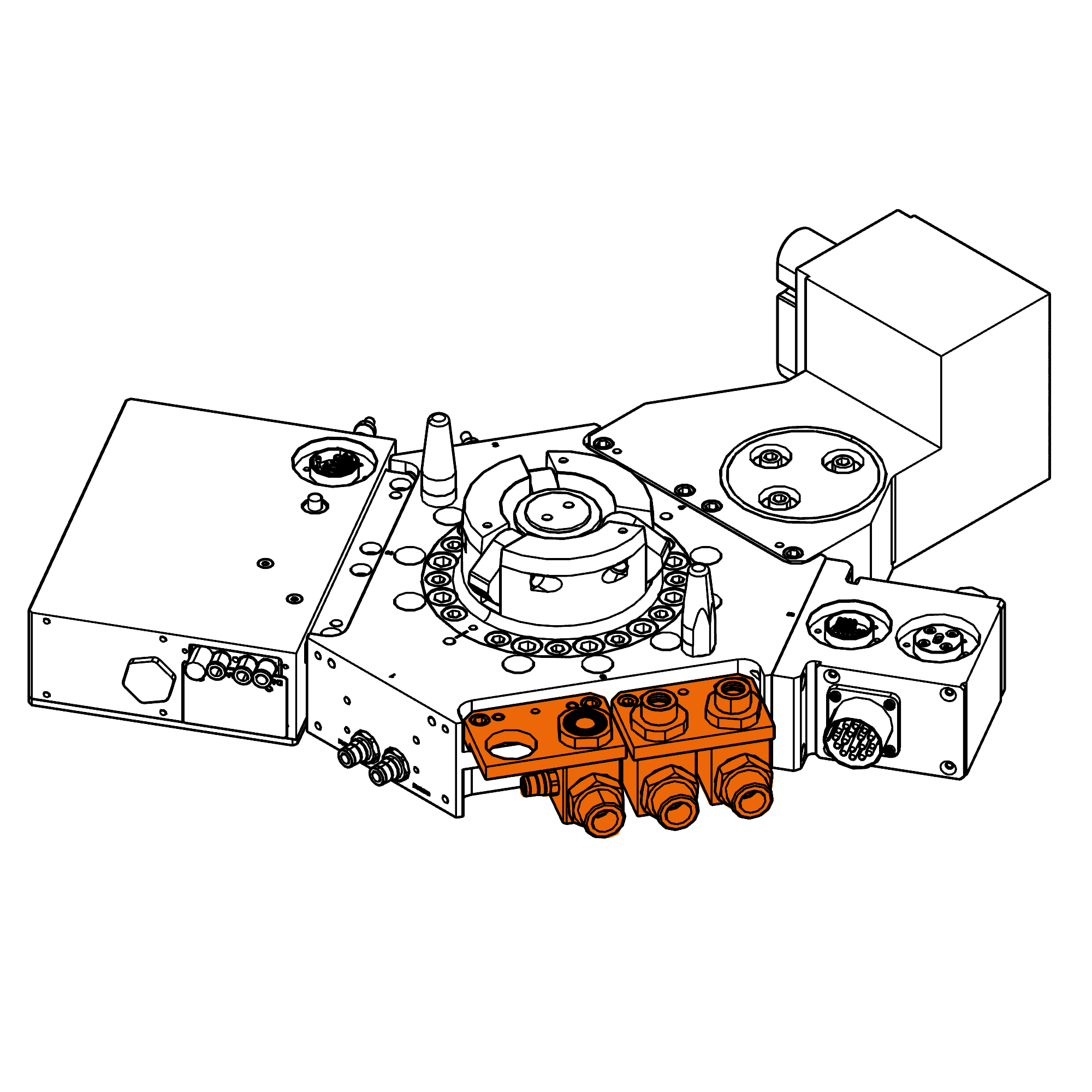
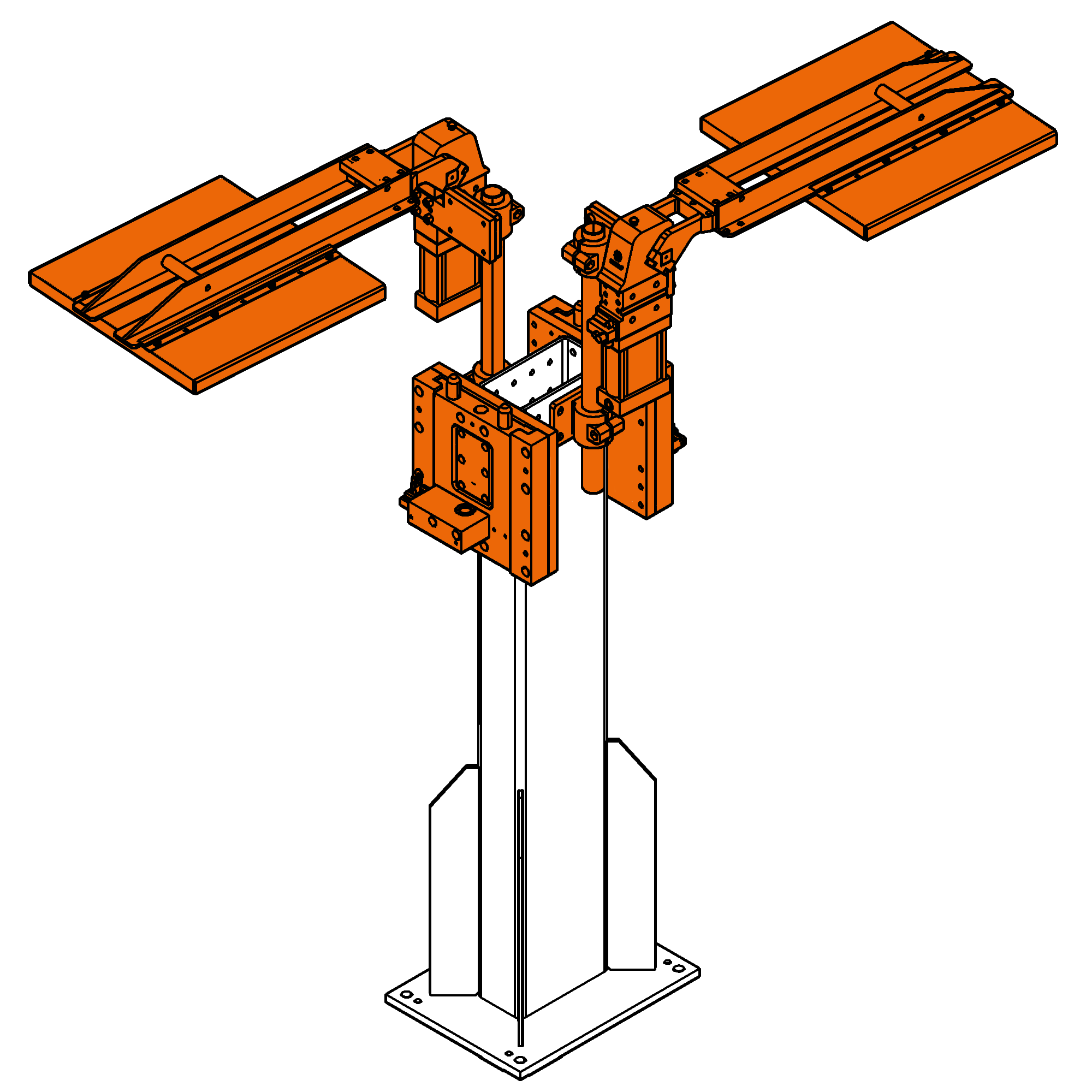
The GP and GPS (stainless steel) Series multiple passage rotary unions are available in 2, 3, 4, 6, 8, 10 & 12 passage models. They meet highly demanding requirements in terms of pressure and rotating speed for applications with liquid, air or vacuum. Modified or specialized configurations are also available.

All GP and GPS Series rotary unions incorporate exclusive DynaSeal™ seals, which are suitable for vacuum and bidirectional pressures up to 51.5 MPa (515 bar). 
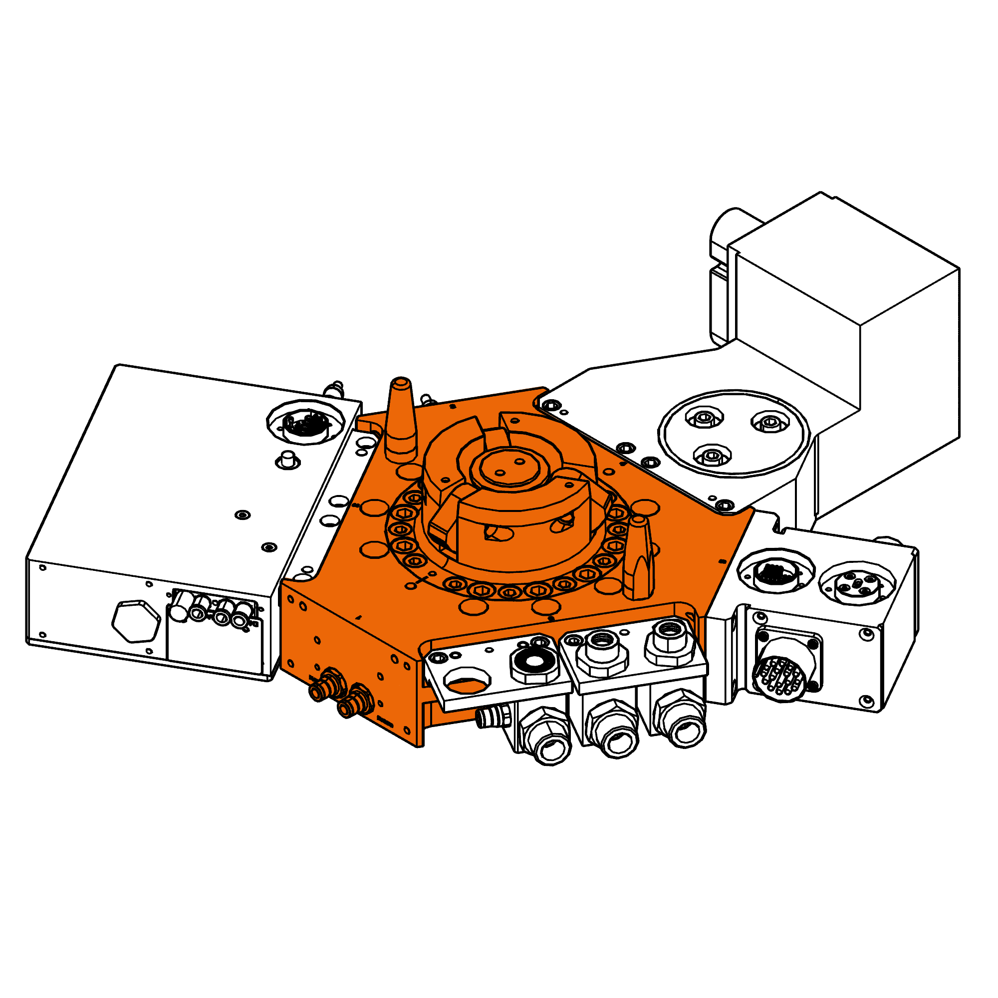
All passages are individually sealed to allow use with dissimilar medias. They can be combined with a wide range of standard or custom slip rings.

Advantages

  • Multipurpose solution for air, gas, oil, water or vacuum
  • Easy integration
  • High performances (pressure, rotating speed)

Benefits

  • Avoid the need of complex piping arrangements
  • Increased machinery performances
  • Paiping maintenance mitigated

GP(S) 131
TypeHydraulic series
Passages3 passages
Connector1/8" NPT
Overall Diameter
74.6 mm
Overall length
106.3 mm
Min Torque
3.39 Nm
Passage Size
4.0 mm
Maximum Pressure151.5 MPa (515 bar)
Maximum Vaccum130 HG
Max Speed1500 rpm
Temperature Range1-18°C à 105°C

1Values are dependent on a combination of all application parameters. Please consult PES.
2Applications with temperatures above 105°C require alternative seal materials. Please consult PES.

General information

GP(S) 131
Connection Sizes1/8", 1/4", 3/8", 1/2", 3/4", 1" NPT
Connection typeNPT & BSPP threads standard. SAE, NPTF, and other thread options are available on a custom basis.
Plating and CoatingBlack oxide plating is standard. Anodized, E-Nickel, Chrome, Nitride, Ceramic and other specialty platings are available as custom options.
MaterialCarbon steel is the standard material for the GP Series, Stainless Steel is the standard material for the GPS Series. Aluminum, Brass, and other materials are available on a custom basis.
MountingThe GP series unions have a unique shaft configuration that consists of individual female tapped passages with an o-ring gland around each for optional flange mounting. There are also tapped holes on the end of the housing for mounting the assembly.

Notice :The provided technical data are the higher limits recommended in static condition. To obtain the correct dimensioning of the product, it is necessary to hold account of all the applicable dynamic forces, including the inertia of the manipulator, the configuration of the tools and the external forces applied.

drawings_plans
3D_steps